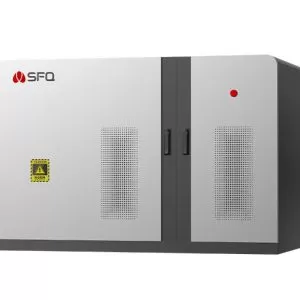
With the development of the PV industry, the ability of inverters to accept grid dispatch has increasingly become a key feature for PV equipment manufacturers and users. String inverters offer flexible active and reactive power regulation capabilities, with an active load rate settable from 0% to 100%, and selectable active power overload output capacity of 1.1 times. In capacitive or inductive states, the maximum reactive load rate can reach 70% P-apparent, and the power factor can be set from 0.8 leading to 0.8 lagging. They also feature multiple reactive power modes to adapt to the needs of different power plants. They can accept and fully comply with dispatch instructions from the grid to fully meet grid access and control requirements. Inverters achieve independent or coordinated regulation of active and reactive power through control strategies and hardware topology, specifically as follows:

1. Active Power Regulation
Active Load Rate Mode
The corresponding equipment can receive external active power percentage instructions, limiting output power to meet dispatch requirements and cooperate with the power plant's power dispatch requirements.
Over-Frequency Load Reduction Mode
When over-frequency load reduction mode is activated, the inverter adjusts its output power according to changes in the grid frequency. When the grid frequency exceeds 50.03Hz, the active power output is reduced at a preset slope (e.g., 40%Pn/Hz), with power decreasing by 40% for every 1Hz increase in frequency. The maximum over-frequency load reduction limit can be set to 20%Pn. Over-frequency load reduction requirements comply with NB/T 32004-2018 and can be flexibly set to adapt to power plant needs.
High-Voltage Grid Load Reduction Mode
The photovoltaic inverter can also be set to high-voltage grid load reduction mode. By setting the high-voltage load reduction point, the machine can automatically reduce power based on the grid voltage. By reducing load in advance, the risk of excessive grid voltage is reduced. Automatic load reduction is performed based on voltage thresholds (e.g., U1, U2). When the voltage rises to U1, power reduction begins at a slope, and at U2, power is reduced to the minimum.
2. Reactive Power Regulation
Fixed Power Factor (PF)
The inverter can control reactive power output by setting a fixed power factor. The power factor is adjustable from -1 to -0.8, or 0.8 to 1, meaning it maintains the set power factor (e.g., 0.8 lagging to 0.8 leading) while outputting reactive power.
The inverter's rated active power output Pn = 150kW, maximum active power output Pmax = 165kW, maximum apparent power output Sn = 165kVA, and maximum reactive power output range is -99kVA to 99kVA.
Voltage Reactive Power Regulation (Q(U))
Reactive power output is dynamically adjusted according to voltage changes; reactive power decreases when voltage increases and increases when voltage decreases. The inverter can achieve the goal of output reactive power varying with grid voltage by setting a voltage-reactive power curve. The QU curve has four voltage points U1, U2, U3, U4 and two reactive power points Q1, Q2. By configuring these points, different voltage-reactive power relationship curves can be achieved.
Active and Reactive Power Coordination (Q(P))
Reactive power is adjusted according to the proportion of active power output. For example, in a photovoltaic power station, reactive power is output at 30% of the active power output. The inverter can achieve the goal of outputting reactive power that varies with active power output by setting active and reactive power curves. The QP curve can be set with up to 5 active power points P1, P2, P3, P4, P5 and 5 reactive power points Q1, Q2, Q3, Q4, Q5. By configuring these points, different active and reactive power relationship curves can be achieved.
Reactive Power Compensation Technology
Reactive power compensation technology compensates for the reactive power demand of inductive loads by connecting capacitive loads (such as capacitors) in parallel, thus balancing the reactive power of the system.
3. Technical Implementation Basis
Hardware Topology: The IGBT inverter bridge reconstructs DC power into AC power through high-frequency switching, combined with an LCL filter to reduce harmonics.
Control Algorithm: Droop control is used to simulate the characteristics of a synchronous generator, achieving PQ decoupling regulation; virtual synchronous machine control enhances grid stability.
Intelligent Dispatch: Supports RS485/wireless communication interface, dynamically adjusting output upon receiving grid commands.
Through the above strategies, the inverter can flexibly respond to grid demands, supporting the efficient operation of renewable energy systems.


One step to find us,we will respond within 24 hours.
More Contact Details
008613738639386
[email protected]